I spent 12 years in the bike industry (mid 80’s to late 90’s), mostly working in R&D and design. I primarily designed and manufactured components but also designed and built frames, including road bikes, mountain bikes (rigid and suspension), time trial frames, and even a lugless fillet brazed BMX frame. I didn’t drive a car during this 12 year span and averaged nearly 15k miles per year on a bike. This was a fantastic time to be in the industry as mountain bikes were very new and suspension was just coming into the market. Nobody really knew what they were doing and we had an absolute ball doing it. Most of this info is pretty old and while the technology has certainly changed the basics really haven’t. I probably have at least four or five different suspension bike designs I’d like to build…
Custom road bike
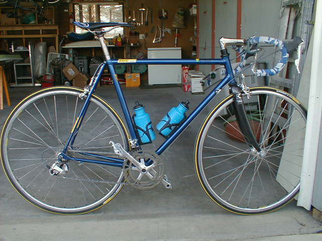
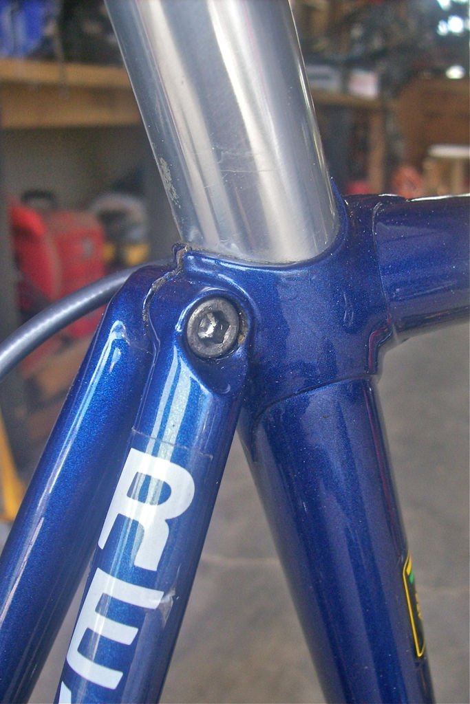
I’ve been riding my own home built bike frames for a long time. I built this steel road racing frame back in 1995 and it’s still going strong.
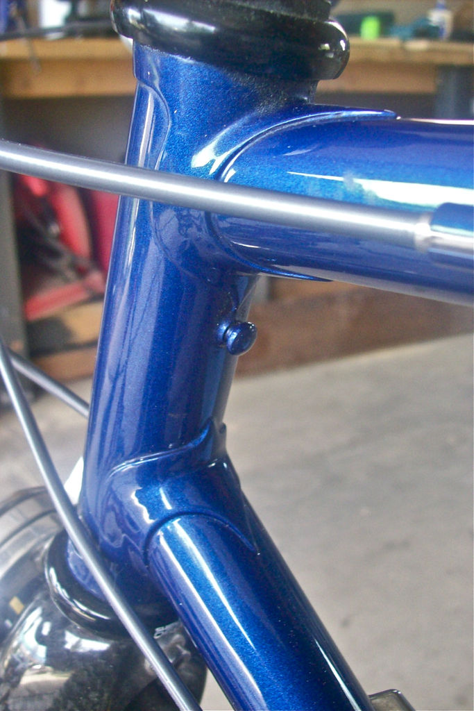
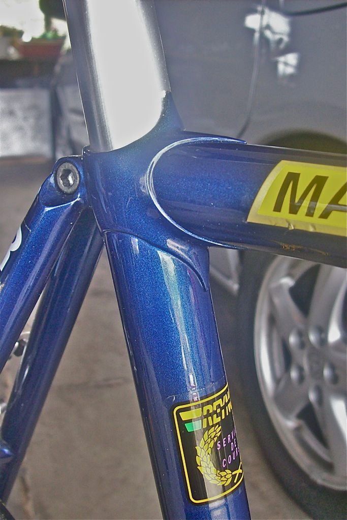
This frame was silver brazed using an oxy/acetylene torch and all the tubes were mitered by hand using a file and a hack saw. I made a simple jig to hold the tubes in place while the frame was tacked together. The frame is a mix of Reynolds 531 for the seatstays/chainstays, Reynolds 653 for the top tube and down tube and 731OS for the seat tube. The finished weight (not including fork) came in around 3.75 lbs.- not too shabby for a 56cm frame with an oversize top tube. The lugs came from Henry James and the dropouts came from a friend who is a frame builder. The dropouts are kind of neat as they have a deep socketed joint for the chainstays and seatstays. The fork is a carbon fiber Kestrel EMS Pro.
I tend to build my road bikes with pretty relaxed geometry since that’s always worked well for me. I have a long femur and I need the seat to sit far back so this bike has a relaxed seat tube angle- 72.5 degrees. The head tube angle is 73 degrees and with a 56cm top tube length I can get a really nice comfortable ride and still get a good handling bike. The oversize (1.125″ OD) top tube makes a big difference in handling- the old 1″ diameter top tubes made for a pretty flexy bike with this relaxed geometry.


Tension Link suspension bike
(Note- this was written ages ago and we’ve learned a LOT since then.)
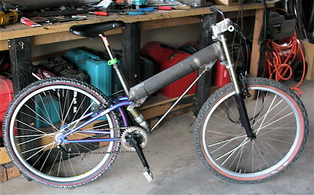
This was an early URT (unified rear triangle) suspension bike design of mine- the original prototype “proof of concept” version was built in 1994. The Tension Link is an open source suspension bike design- it is released under a Creative Commons Share Alike 3.0 license and it is free for anyone to use in any manner they wish as long as they credit the source of the design. I fully encourage people to modify it and improve upon it. My reason for creating this design was to build a suspension bike with good performance that features simple/very low cost construction, has minimal maintenance and can be easily customized in terms of sizing and geometry. There are several reasons for open sourcing the design but the main reason was to be able to make it available free of charge to all the small custom builders out there- the design is really well suited to the needs of the small custom builder that wants to offer a niche market suspension bike but maybe has been put off by the expense, complexity and patent infringement issues of other designs.
A properly designed URT can work quite well for a short travel suspension mountain bike. I wanted a short travel design that has an up/rearward axle path with minimal chain growth- four inch travel is really about the practical limit for this design (five is possible with compromise). There are several ways to achieve this- a gearbox design or a roller placed near a high pivot would work but I felt those designs were best suited toward downhill bikes. In the end I came up with a design that has similar kinematics to a floating BB design with the simplicity of a URT. With this design the main pivot sits directly over the BB and is close to the rider’s center of mass so the suspension is always working, even when you stand so the suspension is very active like a floating BB bike -unlike the old URT designs which were not active at all.
With regard to URT pivot placement the further forward the pivot is the better the pedaling will be but the suspension will be less active- pretty obvious. If the pivot is behind the BB the bike will be very difficult to pedal unless you have a lockout device or massive amounts of low speed compression damping. The best place for the pivot with regard to balancing suspension compliance and rider input is directly above the BB, so when you have some suspension sag the BB is actually slightly behind the pivot. The closer you put the pivot to the BB the less the BB moves and the less interaction you have during suspension movement. The flip side to having the pivot near the BB is that the bike will squat pretty bad when you stand up to pedal, so you need some low speed compression damping to counteract this. As the pivot is raised from the BB the squat becomes less noticeable, but then you have more BB movement. Having the BB move around during pedaling takes some getting used to- some people hate it and some people don’t mind it.
With a URT there is also zero chain growth, so a belt drive system could be used as could an internally geared hub or even a single speed system -without the need for any kind of tensioner.
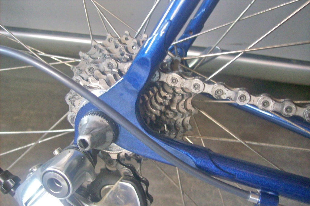
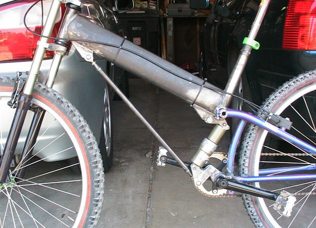
This design has a large torsion tube for the front end and a simple triangulated rear end. This allows for a very efficient structure in terms of torsional stiffness and it is very simple to construct. All loads are fed into the ends of structural members so the design can be very light weight and unlike many designs, this bike can be built with very short chainstays- the “proof of concept” prototype has 15.75″ chainstays with a 26″ wheel and still has decent tire clearance. Altering the frame size does not significantly alter the position of the suspension system components, hence it does not need to be completely redesigned for every frame size. It also has a very low stand over height.
How the suspension works: as the rear wheel hits a bump it moves upward and backward and the BB moves with it, causing the pull rod/radius arm (tension link) to actuate the rocker arm that compresses the shock. It’s a very simple and effective system that pedals very well and is still very good at soaking up large square edged bumps. Everyone that has ridden it has been amazed by how nice the bike rides (even with ancient suspension components) and everyone has expressed a great deal of surprise in regard to its excellent torsional stiffness.
Damping
With regard to how suspension systems work, in a perfect world you want the tire to go over bumps with no change in load. However, from a perspective of attitude/control, you want no compliance whatsoever, so all suspension settings are ultimately a compromise between having as much compliance as possible and as much stability as possible. Rebound damping unloads the tire whenever the suspension has an extension velocity, resulting in reduced grip on the downhill side of a bump- too much rebound damping and the tire loses grip. Too little rebound and the suspension extends too rapidly, causing loss of grip and chassis instability.
Compression damping also does this because when the suspension resists compression, the sprung mass (rider and frame) has a greater upward velocity on the uphill side of the bump. Too much compression damping and the tire loses contact with the ground at the crest of the bump. It’s always a balance. As a general rule, the response to large bumps is controlled by high speed damping (meaning high damper piston velocity) while the overall attitude of the bike (chassis stability) is controlled by low speed damping (meaning low damper piston velocity.) So, bump inputs are at high velocities and rider inputs are at low velocities. So if your bike design is able to minimise rider inputs due to chain/weight transfer forces (braking/accelerating) then you have greater overall chassis stability. What platform dampers try to do is discriminate between rider inputs and bump inputs to give better levels of chassis control. Ideally you would have a damper (shock absorber) that can discriminate between high velocities and low velocities using a frequency threshold. This would give high levels of platform control with reduced fluctuations in contact patch load from bump inputs. This is essentially what platform damping tries to do.
I could be completely wrong about this but I think the problem with current platform damping is that it tends to set a threshold and then over damp anything below that threshold in order to improve pedaling performance (due to rider weight transfer- every bike I’ve ever ridden bobs when set up for good small bump compliance) when what we really want is a damper that can discriminate between a rider input and a bump input without harming small bump sensitivity. Koni developed a frequency selective damper (FSD) several years ago and has recently put it into production for motorsport use. It would be pretty neat to see the technology applied to a mountain bike damper. It wouldn’t be too difficult to measure the frequency at the damper for different weight riders but providing an adjustable or replaceable valve to allow the rider to tune the damper to that frequency would be a formidable challenge. 07/2014 Update- BOS is now using frequency damping in their fork. I’d be curious to know if they licensed the Koni system or developed their own as well as how it is different from the Koni FSD system.
When designing a bike, you also have to take into account the amount of mechanical friction in the suspension system. This is known as Coulomb (friction) damping. Coulomb damping is independent of velocity and is digressive at low velocities. A bike design with multiple pivots will inherently have more of this than a simple three pivot swingarm bike. Detail design (bearing systems, etc.) is very important here and can greatly affect damping.
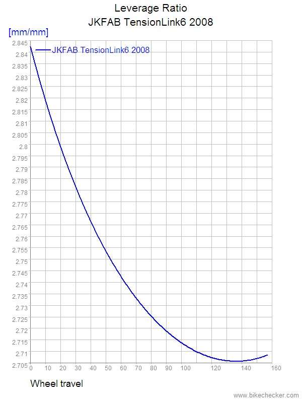
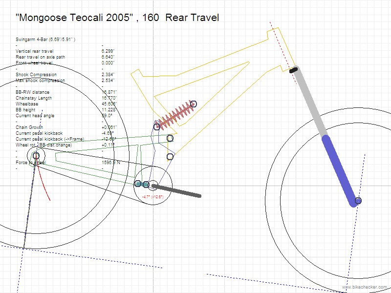
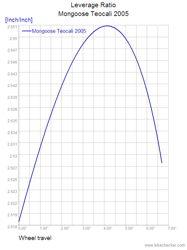
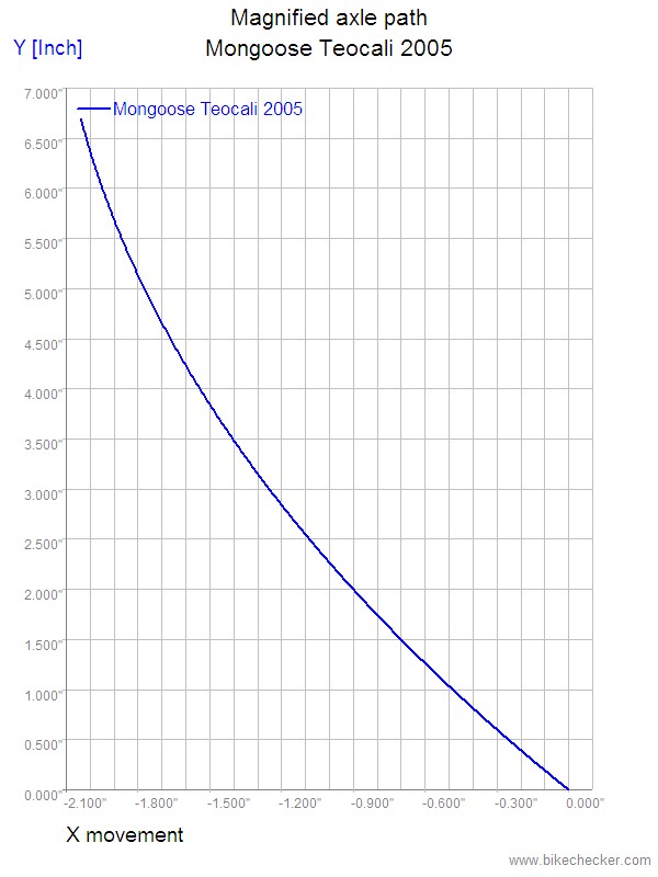
While this design is easily built from chromoly steel (allowing for easy customization) it can also be constructed from Aluminum or carbon fiber for much greater weight savings. The prototype has 3.5 inches of travel but it can also be built with increased travel with a longer stroke shock. The schematics below show the design for a 6 inch travel version. I built the first version of this bike in 1994 and later hacked together the second version shown here. The original prototype had 3″ of travel and a Noleen shock and it was a multi tube frame design instead of the simpler single torsion tube. Here are the drawings and leverage ratio plot for the 6 inch long travel version done in the program Linkage. It is interesting to note that the kinematics of this design (BB and pedal movement relative to rear axle position) are similar to that of the Mongoose Freedrive floating BB system (a design that gets consistently good reviews.) For comparison, the difference between the two designs regarding BB movement at maximum suspension compression is approximately .12 inches. Both designs have very little change in leverage ratios as the suspension compresses, with the Tension Link design being slightly more progressive.
The program Linkage is available here- http://www.bikechecker.com/home.phtml
The file for the Tension Link bike has been uploaded to the Linkage database so people can download it and modify it as they wish- all of the critical frame dimensions and suspension design parameters can be viewed in the Linkage program.
Here are the diagrams for the longer travel Tension Link bike-


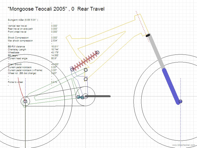
And for comparison here are the diagrams for the Mongoose Freedrive bike (note that this diagram was not done by myself so I cannot 100% verify its accuracy but it should be close enough for the sake of comparison.)
In summary, the Tension Link design has some advantages:
*ease of construction/fixturing and minimal welds
*up and rearward axle path
*ability to construct small frame size- easily down to 14″ effective seat tube length
*low center of gravity/good mass centralization
*low stand over height
*direct load paths- can be constructed to be very light weight and have excellent torsional stiffness
*all loads are fed into the ends of frame members
*can be built with very short chainstays- prototype stays are 15.75″
*can be built with 26″ wheels or as a 29er/650B, geared bike or single speed
*simple/clean cable routing
*excellent tire clearance
*can be built with cantilever or disc brakes
*suspension is active whether you are sitting or standing
*linkage is easily modified to vary compression curve
*pull rod (tension link) is loaded primarily in tension so it can be very light weight
*frame members can be constructed from a wide variety of materials (4130 steel, carbon fiber, Titanium or Aluminum)
*frame size does not greatly affect suspension linkage geometry
Specs for the prototype are:
4″ front travel
3.5″ rear travel
15.75″ chainstays
12.75″ BB height
69 head angle
73 seat angle
23″ top tube
Here’s a video of how it works-
Pictures of the 2nd generation “proof of concept” prototype-
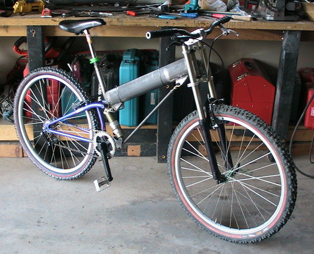
Additional information about the prototype bike I built can be found here- http://www.instructables.com/id/How-I-built-a-suspension-mountain-bike/
For a good discussion of bicycle suspension systems have a look here- http://members.home.nl/vd.kraats/ligfiets/pa/index.htm
There is a good discussion of URT/floating BB designs here- http://www.rdrop.com/users/twest/mtb/#Introduction
This is a simple design for a long travel downhill bike with a high pivot and very linear leverage rate. When talking about suspension bike design one of the most important things to discuss is wheel rate. It’s important because you want a balanced bike- if the front and rear wheels have significantly different wheel rates the bike can become unstable/unpredictable.
Wheel rate = (leverage ratio)squared x spring rateIn this case at the beginning of travel the ratio is 2.603:1 and I’m using a spring rate of 300 lb/in so:
Wheel rate = (1/2.603)squared x 300 lb/in so the wheel rate works out to 44.28 lb/in which is right about where a Fox 40 fork would be (using a 45 lb/in spring) for a 180lb rider.
As the suspension moves through its travel the leverage ratio changes, changing the wheel rate. At 3.5″ travel the ratio is 2.651:1 so we get a wheel rate of 42.69 lb/in and then the rate ramps back up to give a final wheel rate of 44.34 lb/in.
So this is a very linear design that would work pretty well with a Fox 40 fork with a green 45 lb/in spring. It would get ever so slightly softer for the first 3″ and then slightly firm up for the rest of the suspension travel. I tend to like bikes that are linear or slightly progressive- that’s just me and another rider may prefer something else. The shock linkage on this design is very easy to modify to change the suspension characteristics.


Due to the high swingarm pivot I had to have an idler pulley to align the chain pull force to get a proper amount of anti-squat. Anti-squat balances out the effects of mass transfer on the suspension during acceleration. I had to play around with various pulley setups in multiple gear combos to get proper pedal feedback. With a 28 tooth rear cog the pedal kickback is +10.17 degrees (anti-squat @132% to 108% throughout the travel) and with a 12 tooth rear cog it’s -3.25 degrees (anti-squat @ 88% to 60% throughout the travel) so those are the two extremes, which is pretty good. In the middle cogs pedal feedback is very minimal- less than 3 degrees and I can still get 100% anti-squat. By changing the size of the guide pulley I can manipulate the amount of anti-squat/pedal feedback.
The pivot is exactly 9″ directly above the BB so it looks high but it gives an axle path that is similar to the front wheel. It’s really all about axle path. I’ve built more than a few frames with a similar axle path and I’ve always liked the way they ride. I do think it absorbs square edge bumps better due to energy dissipation (for lack of a better term.) Remember that since dampers are speed sensitive (not load sensitive) the shape of a bump is more important than the size of a bump and a rearward axle path puts less energy into the damper than a vertical axle path for a given sized square edged bump. I also think that the geometry of the high pivot simply absorbs bumps better because it’s a more natural motion for the wheel to take.
Since Energy = [1/2 x Mass x (Velocity)squared] the upward velocity of the rear wheel with a rearward axle path will create less energy over a given span of time than that of a rear wheel with vertical axle path for a given shape bump. Since a large square edged bump requires a very rapid increase in damper shaft velocity I think a high pivot swingarm design has a distinct advantage over a low pivot swingarm design (but only regarding that particular situation) because the increase in damper shaft velocity isn’t as rapid- hence I think it may be easier to maintain better chassis stability without having to resort to something like severe digressive damping (similar to a very rapid shim stack blow off) or regressive damping (which provides lower damping rates at high damper piston speeds.) Digressive damping means that the damping force increases with absolute velocity at a decreasing rate. Mid to high velocity digressiveness allows for a more controlled feel with less harshness when hitting big bumps but there could be a trade off in stability if you go too far as the bike could become unsettled or unpredictable. Modern bike dampers are pretty darn good though when properly matched to a given design, so we’re getting really nitpicky here…
I think there might be some merit to regressive damping if you could separate spring and damper forces by having the wheel rate linear and the damping regressive but that would require separate mounting of the spring and damper, which really isn’t practical for weight and packaging reasons (but I’m working on it.) Now granted I’m not a damper engineer so I could be way off base here but let’s say you have a low pivot swingarm bike that has a vertical axle path and you go into a bumpy corner hard. The bike will more than likely have a fairly progressive wheel rate. Now you start hitting some of those square edged bumps and I’m willing to bet that the bike hangs up. Bump inputs like that are at high frequencies and the damper can’t cope with it in that situation because the suspension is already heavily loaded- this is where regressive damping might help- and this is where a rearward axle path with a linear rate would really shine. As far as I know, both Ohlins and Penske have been working on regressive damper valving for the last few years and I believe Penske recently filed for a patent. No idea if it will make its way into bike dampers… Update 06/2014- Trek/Fox have partnered with Penske and are introducing regressive damping.
I think that’s why we’re seeing more and more long travel bikes with short bar four link systems- it allows the designer to better manipulate axle path and anti-squat values, but you can still only go so far in terms of rearward axle path without using an idler or gearbox due to chain extension. So these bikes tend to start out with a rearward axle path for the first half of the suspension compression and then go more vertical/inward to manage chain extension.
This is a highly debatable point, but I also think a rearward axle path does a good job of managing weight transfer by keeping wheelbase more constant -assuming you could actually get a perfect linear axle path parallel to the front fork (this design is close enough for me.) I say it’s debatable because you never really have the front and rear suspension compressing the exact same amount at the exact same time, so the wheelbase is constantly changing no matter what type of suspension system you have- the goal is to minimize it because no rider can react fast enough to a radical weight transfer shift caused by an imbalanced suspension system. By trying to minimize weight transfer you’re going to have a more stable bike that handles better, especially as speed and travel increases. With a low pivot swingarm bike (vertical/inward axle path) I’d be inclined to have a more rising rate suspension since weight transfer will shift a bit more rearward as the suspension compresses vs. a rearward axle path bike will probably be more linear rate since the rearward weight transfer wouldn’t be as severe.
In some ways it’s like racecar design where you’re always trying to maintain a consistent aerodynamic center of pressure except with a bike you’re trying to maintain a consistent center of traction/center of mass. It’s all about proper balance and manipulation of weight transfer under acceleration, braking and bump forces.
The other thing I like about the pivot placement is that there is a very direct load path from the head tube to the rear axle. Structural efficiency has always been important to me and I always try to have designs that have good specific torsional rigidity.
The downside to the high pivot is chain extension/pedal feedback so you have to have an idler pulley or gearbox to minimize this. The increase in friction is a definite disadvantage but I feel that an idler pulley is worth the trade off in this case and is still more efficient than a gearbox. So while high pivots can work for DH bikes they really don’t belong on traditional XC/AM bikes due to drive train inefficiencies- the only exception being a URT or floating BB bike. The other issue is the suspension stiffens a bit under braking but fitting a brake torque arm can cure that (of course that adds additional friction into the system as well- there’s always a trade off…)
The geometry of this design is pretty standard stuff- this is with a 2.7 front tire/2.5 rear tire and 7″ front travel (since that’s what my Super T fork is) and 8″ rear travel-
Head angle 65.7
Wheelbase 44.5″
Chainstay 16.5″
BB height 13.78″
TT length 23.5″
At first the wheelbase may look a bit short, but with the increased stability of the high pivot I don’t think it will be a problem. The other reason is that wheelbase (along with traction) ultimately determines turning ability and high pivot bikes don’t usually want to turn as well as low pivot bikes, so a shorter wheelbase can help compensate for this. Everything is a compromise in bike design and you have to look at how the whole system works together. Torsional rigidity, tire clearance, geometry, friction, etc. all play important roles. Every system out there has it’s positives and negatives- you just have to find what works best for you.
Real Design
After leaving Onza four of us former Onza employees started a company named Real Design. My job was design engineer/creative director- I designed components, built prototypes, sourced manufacturing and did art direction for advertising/packaging design.
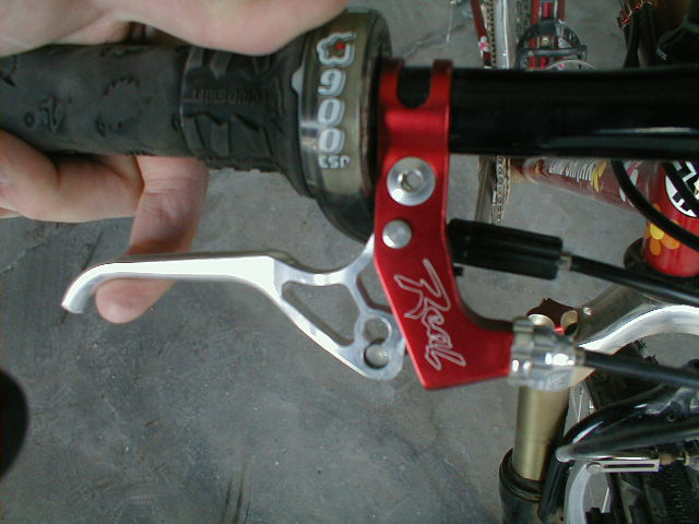
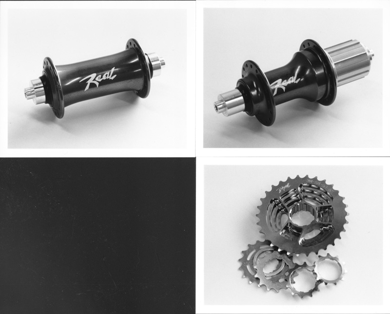
Here are some of the projects I worked on including hubs, brake levers, bottom brackets, chainrings and cassette gears.
The 2nd gen brake lever (X-Lever) was probably my favorite product as it really fulfilled all of the design requirements quite splendidly. It was very light weight, incredibly durable, had excellent ergonomics, worked with a wide variety of brake systems, had almost no friction and it was simple to manufacture.
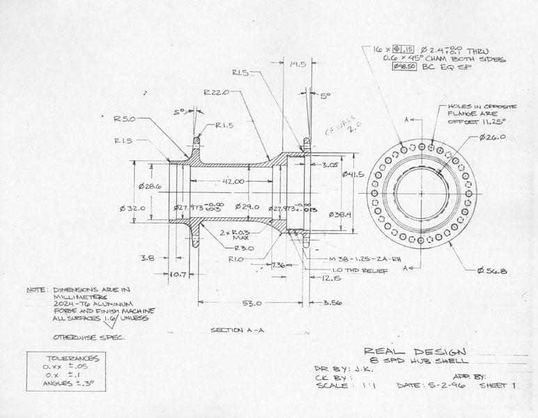
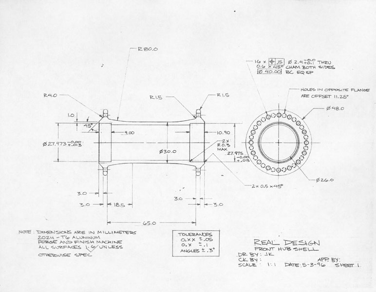
The hubsets were designed from the perspective of a bike shop mechanic/wheelbuilder ( I had built hundreds of wheels.) They had forged hub shells (which made them good for radial lacing), good quality seals/bearings, needle roller bearing supporting the drive hub and they were simple to take apart and service. They were pretty light too.
The cassette gear cluster was an oddball product. The smaller cogs were steel while the larger cogs/body were machined from a single Aluminum forging (an industry first.) It was crazy light but the Aluminum cogs just didn’t hold up well to the rigors of mountain biking with mud and dirt. It was sold as a “race day only” product. It is interesting that now there are several one piece body designs on the market.
The first bottom bracket assemblies produced were nothing special. The 2nd generation was interesting in that the bearing cups could accept up to four bearings and the spacer/wave washer assembly reduced side loading/binding as not two bikes ever had the exact same width BB shell.

The chainrings proved to be one of most popular products. These were machined from solid Aluminum plate and received a very durable electroless nickel finish.

Onza
During my time at Onza in the early 90’s I worked in research and development and worked on cranksets (Titanium and Aluminum), tire designs, brakes, bar ends and clipless pedals.
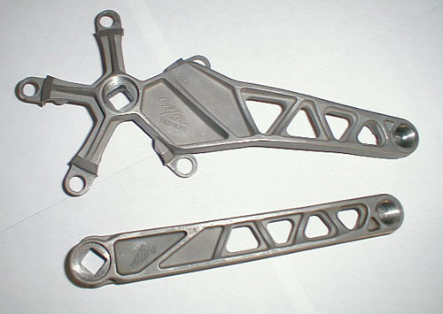
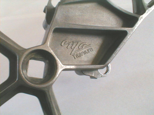
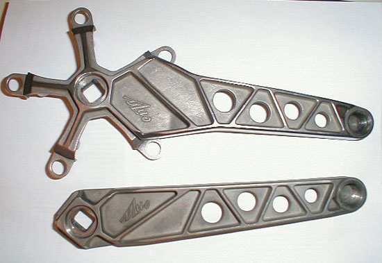
The fabled Onza Titanium crankset. These were cast in 6Al/4V Ti. This was the stuff of legend and I still hear all kinds of stories about these to this day (most of it wrong.) This project was already underway when I began working at Onza. The 1st gen crankset is the one with the round holes- these cranks had several problems: the pedal hole was too shallow and the taper would bottom out on the BB spindle. These tended to fracture near the pedal spindle. The 2nd gen cranks had triangular windows- and these also fractured near the pedal spindle. This is where I came in. The first step was to verify the design loading using non destructive testing- this was done on a laser interferometric holography rig at AiResearch.The problem turned out to be the casting process (which was my initial assessment- long story behind that.) Even with chem milling and hot isostatic pressing they simply could not survive the stress. Since forging was out of the question due to cost I had two sample sets machined from solid (I got a deal on production material from Oremet) and recommended a shot peened finish. The plan was to test them to failure on a purpose built load test rig and compare the results to the leading market Shimano XT crankset at the time. If they passed I had a plan written up to produce a limited run of 1000 units. In the end the machined samples were produced ( I heard they were gorgeous) but never tested to my knowledge- I had already left to start Real Design. A total of around fifteen prototype cranksets were produced ( I broke two sets myself on my own bike.) They were never offered for sale. There were two Aluminum versions, one early version which was extremely overbuilt and another that I did drawings for that was to be forged and produced in Taiwan but it never came to be.
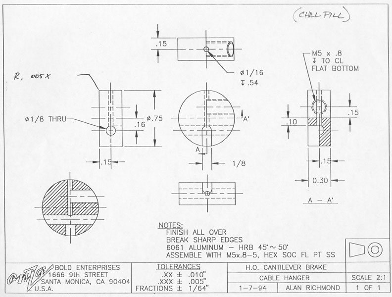
The Chill Pill was a cable hanger I machined one afternoon as we needed a cable hangar for the new H.O brakes. I made several sets of these for pro riders to test out and production started very shortly afterward.
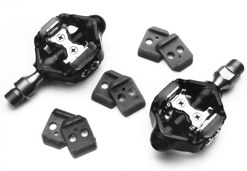
The H.O. clipless pedal. Some people thought these were the best thing ever and some people hated them. I had sold a clipless pedal design to Onza (how I got hired) but it was never used as the H.O. pedal was well under development in Taiwan. I was brought in to help iron out production problems. The biggest problem was the tolerance on the height of the base plate relative the the elstomer/stainless cleat retention plates. If it was off by more than about .0025″ the pedal simply would not work. The other problem was the elastomers would turn rock hard in cold weather. The pedal body was structurally sound and they were very light weight, especially the Titanium spindle version. I had already begun a complete re design of the pedal using traditional wound springs but had already left the company before it went any further.
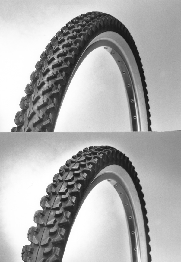
The Aggro (front) and Honch (rear) tires. This was the first project I worked on at Onza. I did about thirty drawings for these tires, showing individual knob designs as well as casing profiles. These tires were designed for hardpack conditions (they were terrible in mud) and they were very fast with excellent cornering grip due to the side knob design and consistent spacing. The rubber compound was fairly hard for the time (69 durometer.)